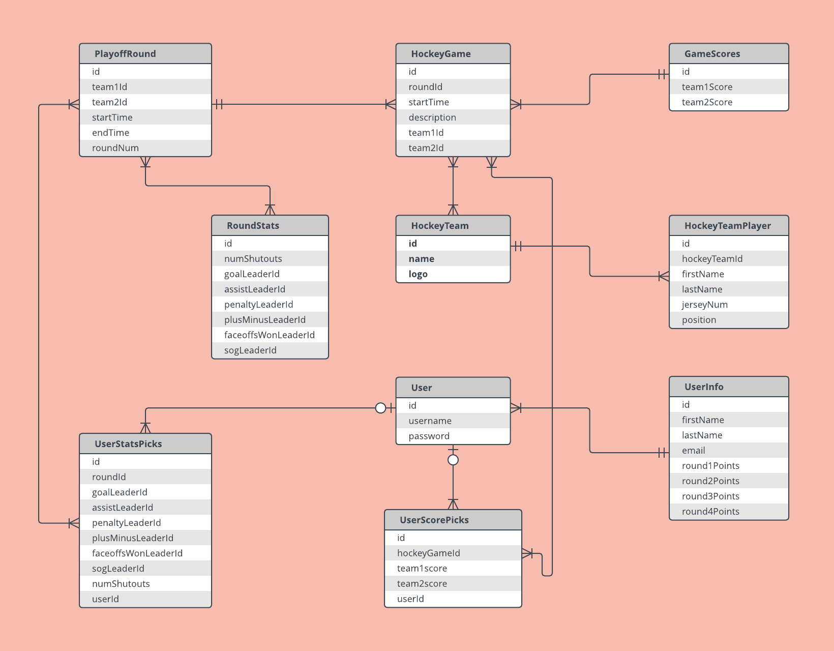
-
Entity Relationship Diagram(ERD)Modeling 2019. 8. 25. 11:53
1. Overview
An entity-relationship diagram (ERD) shows the relationships of entity sets stored in a database. An entity in this context is an object, a component of data. An entity set is a collection of similar entities. These entities can have attributes that define its properties.

2. Description
2.1 Entity
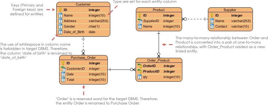
An ERD entity is a definable thing or concept within a system, such as a person/role (e.g. Student), object (e.g. Invoice), concept (e.g. Profile) or event (e.g. Transaction) (note: In ERD, the term "entity" is often used instead of "table", but they are the same). When determining entities, think of them as nouns. In ER models, an entity is shown as a rounded rectangle, with its name on top and its attributes listed in the body of the entity shape. The ERD example below shows an example of an ER entity.

2.2 Entity Attributes
Also known as a column, an attribute is a property or characteristic of the entity that holds it.
An attribute has a name that describes the property and a type that describes the kind of attribute it is, such as varchar for a string, and int for integer. When an ERD is drawn for physical database development, it is important to ensure the use of types that are supported by the target RDBMS.
The ER diagram example below shows an entity with some attributes in it.

2.3 Primary Key
Also known as PK, a primary key is a special kind of entity attribute that uniquely defines a record in a database table. In other words, there must not be two (or more) records that share the same value for the primary key attribute. The ERD example below shows an entity 'Product' with a primary key attribute 'ID', and a preview of table records in the database. The third record is invalid because the value of ID 'PDT-0002' is already used by another record.

2.4 Foreign Key
Also known as FK, a foreign key is a reference to a primary key in a table. It is used to identify the relationships between entities. Note that foreign keys need not be unique. Multiple records can share the same values. The ER Diagram example below shows an entity with some columns, among which a foreign key is used in referencing another entity.

2.5 Relationship

A relationship between two entities signifies that the two entities are associated with each other somehow. For example, a student might enroll in a course. The entity Student is therefore related to Course, and a relationship is presented as a connector connecting between them.
2.6 Cardinality

Cardinality defines the possible number of occurrences in one entity which is associated with the number of occurrences in another. For example, ONE team has MANY players. When present in an ERD, the entity Team and Player are inter-connected with a one-to-many relationship.
In an ER diagram, cardinality is represented as a crow's foot at the connector's ends. The three common cardinal relationships are one-to-one, one-to-many, and many-to-many.
2.6.1 One-to-One Relationships
A one-to-one relationship is mostly used to split an entity in two to provide information concisely and make it more understandable. The figure below shows an example of a one-to-one relationship.

2.6.2 One-to-Many Relationships
A one-to-many relationship refers to the relationship between two entities X and Y in which an instance of X may be linked to many instances of Y, but an instance of Y is linked to only one instance of X. The figure below shows an example of a one-to-many relationship.

2.6.3 Many-to-Many Relationships
A many-to-many relationship refers to the relationship between two entities X and Y in which X may be linked to many instances of Y and vice versa. The figure below shows an example of a many-to-many relationship. Note that a many-to-many relationship is split into a pair of one-to-many relationships in a physical ERD. You will know what a physical ERD is in the next section.

3. Model
ERD features Conceptual Logical Physical Entity (Name) Yes Yes Yes Relationship Yes Yes Yes Columns Yes Yes Column's Types Optional Yes Primary Key Yes Foreign Key Yes 3.1 Conceptual Model

3.2 Logical Model

3.3 Physical Model

4. References
https://www.guru99.com/er-diagram-tutorial-dbms.html
https://www.visual-paradigm.com/guide/data-modeling/what-is-entity-relationship-diagram/
'Modeling' 카테고리의 다른 글
Class Diagram (0) 2019.08.25